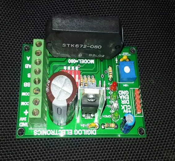
STK672-080 Constant Current Sine Wave Unipolar 6 Wires Stepper Motor Driver
SKU: B 242,,D199,TMD0,Th0,KRT
STK672-080 Stepping Motor Driver Sine Wave Drive Output Current , STK672-080 Unipolar stepper board is high efficient stepper driver for Unipolar stepper motor been design for various application like CNC, robotics, control routers, lathes, mills, PCB drillers and engravers. STK672-080 is a unipolar constant-current chopper type externally-excited 4-phase stepping motor driver hybrid IC which uses MOSFET power devices. It has a micro-stepping operation-supported 4-phase distributed controller built-in to realize a high torque, low vibration, low noise stepping motor driver using a simple control circuit.
Pin Description;
- +5V; 5V OUTPUT .
- CLK Clock Pulses from Mach3 Baord or Arduino
- DIR: Direction Pin Logic 1 for Clockwise and 0 for anticlockwise direction.
- ENA: Enable pin , Logic 0 for enable, Logic 1 for Disable
Output Pins:
- GND: 0V OF POWER SUPPLY
- +: 12V TO 24V INPUT POWER SUPPLY
- COM: A com Wire of stepper motor .
- COM: Center Wire of stepper motor .
- : BB: Coile B wire -B
- : B: Coile B wire B
- : AB: Coile A wire -A
- : A: Coile A wire A
Features:
- Input voltage: DC 12~32V (with a capacity greater than 50W veneer can)
- Input Control signal: pulse, direction, enabled. (Supports common cathode or common anode connection)
- Output current: 0~3A stepless adjustable.
- Subdivision control: full step, two segments, four segments, eight segments, 16 segments. (Where 16 is a pulse subdivision step 2, the proposed eight segments)
- With automatic current control function. (If there is no pulse signal input to the drive, the drive will automatically lock the motor current drops to effectively reduce motor heating and power consumption.)
- Equipped with anti-reverse diode to prevent reverse power input when the burned parts.
- Optical coupling design input jamming circuit, making the entire product more secure.
- Drive to the wiring
- The drive also supply, 12~32V can be
- Drives on the left six ports connected two-phase stepper motor 6 lines, first with a multimeter to distinguish between motor group A and group B, as shown connected to the corresponding port, remember the line of group A and B lines do not dislocation connected, but which of the same group of lines connected +, – it does not matter
for(int i=0;i<5000;i++){ digitalWrite(LED_BUILTIN, HIGH); // turn the LED on (HIGH is the voltage level) delayMicroseconds(500); // wait for a second digitalWrite(LED_BUILTIN, LOW); // turn the LED off by making the voltage LOW delayMicroseconds(500); }
delay(100);
digitalWrite(dir, LOW);for(int i=0;i<5000;i++){ digitalWrite(LED_BUILTIN, HIGH); // turn the LED on (HIGH is the voltage level) delayMicroseconds(500); // wait for a second digitalWrite(LED_BUILTIN, LOW); // turn the LED off by making the voltage LOW delayMicroseconds(500); }
delay(100);


