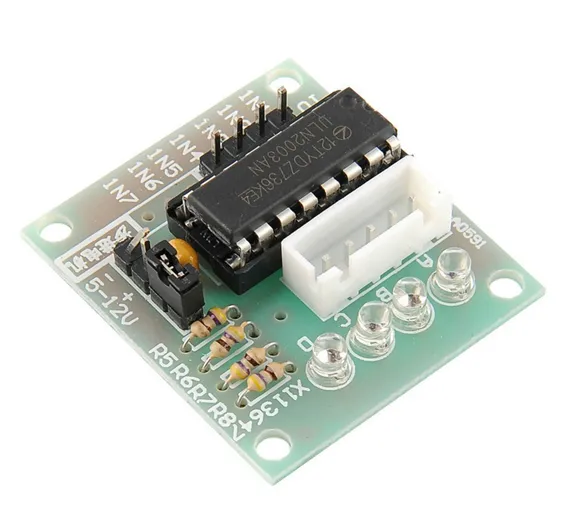
ULN2003 Stepper Motor Drive Unipolar stepper Motor Driver
SKU: B193,D06,IMP200,Th25,KRT07+515,N185
The ULN2003 stepper motor driver board allows you to easily control the 28BYJ-48 stepper motor from a microcontroller, like the Arduino Uno. One side of the board side has a 5 wire socket where the cable from the stepper motor hooks up and 4 LEDs to indicate which coil is currently powered. The motor cable only goes in one way, which always helps.
On the side you have a motor on / off jumper (keep it on to enable power to the stepper). The two pins below the 4 resistors, is where you provide power to the stepper. Note that powering the stepper from the 5V rail of the Arduino is not recommended. A separate 5-12V 1Amp power supply or battery pack should be used, as the motor may drain more current than the microcontroller can handle and could potentially damage it. In the middle of the board we have the ULN2003 chip. At the bottom are the 4 control inputs that should be connected to four Arduino digital pins.
Features
- On-board ULN2003A chipset
- 5-12V power supply
- On-board 4-way indicator light;
- On-board XH-5P socket
- Compatible with Arduino
- Stepper Motor Driver Test and DIY
Specifications
- Rated voltage: 5V to 12V DC
- Number of Phase: 4
- Speed Variation Ratio: 1/64
- Stride Angle: 5.625° /64
- Frequency: 100Hz
- DC resistance: 50Ω±7%(25℃)
- Idle In-traction Frequency: > 600Hz
- Idle Out-traction Frequency: > 1000Hz
- In-traction Torque: >34.3mN.m(120Hz)
- Self-positioning Torque: >34.3mN.m
- Friction torque: 600-1200 gf.cm
- Pull in torque: 300 gf.cm
- Insulation grade A
Motor Connections
- The diagram to the left shows the 5 wires connected to the motor. Plug the motor into the driver board.
- The Arduino should be connected to the ULN2003 driver board as shown below:
- 5V+ connect to +5V
- 5V- connect to 0V (Ground)
- IN1: to Arduino digital input pin 8
- IN2: to Arduino digital input pin 9
- IN3: to Arduino digital input pin 10
- IN4: to Arduino digital input pin 11
Driving the Motor
- You should drive the motor by enabling the pins in an 8-phase order as shown to the left (Clockwise movement):
- Drive IN4 only
- Drive IN4 and IN3
- Drive IN3 only
- Drive IN3 and IN2
- For anti-clockwise motion, simply follow the sequence in reverse

