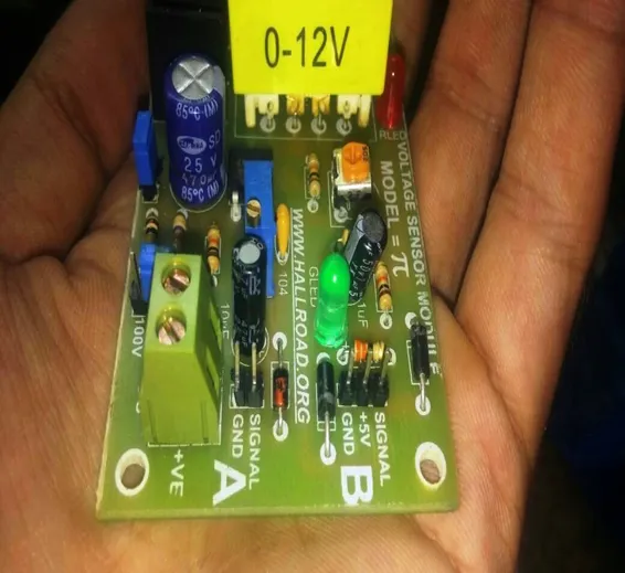
PT Module DC Or AC Voltage Sensing Module Arduino Ac voltage Sensor Module
SKU: B 245, D 40,MFR10,Th5,KRT
You can measure line ac voltages or dc voltage of dc sources like a battery or power supply using this PT Module DC Or AC Voltage Sensing Module Arduino Ac Voltage Sensor Module.
Features of DC AC Voltage Sensor Module:
- Ac voltage range= 0 to 275
- DC Voltage range= 0 to 100
- This circuit has 3 possibilities of use.
- 1 Dc voltage Sensing
- 2 Ac voltage Sensing using Detecting Peak Value of Rectified and filtered sine wave.
- 3 AC Voltage Sensing using Clamping Method And Peak Detecting Without Filtering.
Specifications DC AC Voltage Sensor Module:
- PCB board size: 3 inch x 2 inch
- Rated Input Current: 10mA
- Retardation (rated input): “20' (input 2mA, sampling resistance 100O)
- The linear range: 0 ~ 300V
- Isolation voltage: 1000V
- Operating temperature: -40 ° C- + 70 ° C
1 DC Voltage Sensing:
This circuit has two options, 100V input sensing or 25 voltage sensing.
Its Very simple Circuit, all you need to select your range using jumper and calibration after burning example code in Arduino. This is just divider circuit.
This circuit divides input volts by 10 and gives to your Arduino.
So if Arduino is reading 2.5v, thats mean input is 2.5*10 volts.
Its linear and stable circuit with noise filtering section in it.
2 AC voltage Sensing using Peak Detecting of Rectified and filtered sine wave.
There is no need to power up this section, it just gives ready to use the signal for the microcontroller to measure. The only difference between this circuit and previous is rectification section.
This section converts input AC voltage to DC and gives these voltage to voltage divider section.
3 AC Voltage Sensing using Clamping Method And Peak Detecting Without Filtering.
In this circuit, we are clamping sine wave and adjusting zero degrees of the sine wave to vcc/2 of microcontroller power supply.
This way we get complete sine wave even without losing 0.7v across diodes.
In this board, we can measure and monitor complete sine wave, either there is noise in the sine wave, surge, or power fail.
There is no delay of data, but its microcontroller programmer responsibility to write software for this board, We have given a basic program of Arduino to work for this section, it works nicely for voltage measurement.
Onboard precision clamp circuit , the signal for precise sampling .
Can be measured within the 275V AC voltage corresponding to the analog output can be adjusted
Only one section can be used at a time, DC voltage measurement, or AC voltage measurement also only 1 circuit can be used at a time while measuring of AC voltage because of the ground is different between both sections.
*/
//////////////////////////////////////////////
void setup() {
Serial.begin(9600);
}
//////////////////////////////////////////////
void loop() {// float DC_Voltage=analogRead(A0);DC_Voltage= map(DC_Voltage, 0, 1023, 0, 500); DC_Voltage=DC_Voltage/10; Serial.print(“Dc_Voltage=”); Serial.println(DC_Voltage); // for dc volt
float Ac_Voltage=read_using_dc_voltage_peack(); Serial.print(“Ac_Voltage=”); Serial.println(Ac_Voltage); // for ac volt using simple method
// float Ac_Voltages=read_using_sine_wave();if(Ac_Voltages<0) Ac_Voltages=0; Serial.print(“Ac_Voltage=”); Serial.println(Ac_Voltages); // for ac volt using sine wave.delay(50); // delay in between reads for stability
}
///////////////////////////////////////////////
float read_using_dc_voltage_peack()
{
return(( map(read_peak(A0), 0, 1023, 0, 500))*0.707);
}
/////////////////////////////////////////////////
float read_using_sine_wave()
{
return((map(read_peak(A0), 0, 1023, 0, 1000))-500)*0.707;
}
/////////////////////////
unsigned long read_peak(int pin) // this function gives peak value of voltage on selected pin
{
int temp,j;
unsigned long x=0;
for( j=0;j<510;j++)
{
temp= analogRead(pin);
if(temp>x) x=temp;
delayMicroseconds(50);
}
return x;
}


