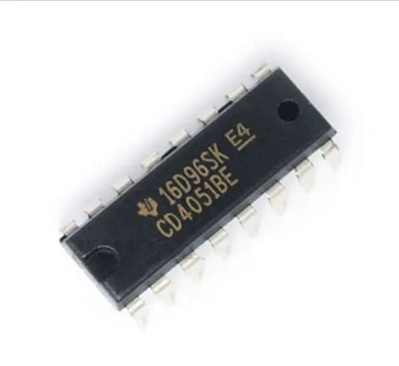
CD4051B CMOS Single 8-Channel Analog Multiplexer/Demultiplexer
SKU: SKU: DBS43,TMD20,Th5,KRT
A multiplexer or demultiplexer enables you to expand the in-and outputs on your Arduino board. The 4051 is an 8 channel analog multiplexer / demultiplexer, thus:
- If you use the 4051 as a Multiplexer: You can choose between 8 different inputs and select just one you want to read at the time.
- If you use the 4051 as a Demultiplexer you can choose between 8 different outputs and select just one you want to write at the time.
Futhermore, the 4051 is able to work with analog values; in the case of the Arduino, you are able to use the analog inputs with a voltage between 0-5V and route them to an Analog-In Pin on your Arduino.
To select the Pin we would like to read or write, we have to use the three Select Pins (S0, S1 and S2). Each of these pins have to be connected to one digital out pin on the Arduino. Every pin is representing a number (S0 = 1; S1 = 2; S2 = 4) and if we set one of these Select pins to HIGH, the number the pin is representing will be transmitted to the 4051. For example:
- If S0 and S1 are HIGH and S2 is LOW pin y3 is selected (1+2+0 = 3).
- If S0 and S2 is HIGH and S1 LOW pin y5 is selected (1+0+4 = 5).
It is not possible to read or write more than one pin on the 4051 at the same time, because you can only select one pin at a time. But you can read and write to the pins quite fast. There is no delay needed between selecting and read or writing the pin.
- Z —– common input/output (connected to Arduino Input/Output)
- E —– enable input (active LOW) (connected to ground (gnd))
- Vee — negative supply voltage (connected to ground (gnd))
- gnd — ground (0 V)
- S0-S2 – select inputs (connected to three arduino digitalOut Pins)
- y0-y7 – independent inputs/outputs
- Vcc — positive supply voltage (5v)
//////////////////////////////////////////////////////////////////////code example
- /
- *
- * codeexample for useing a 4051
- * analog multiplexer / demultiplexer
- * by david c. and tomek n.
- * for k3 / malm� h�gskola
- *
- * edited by Ross R.
- * edited by Igor de Oliveira Sá.
- * /
- int r0 = 0;//value of select pin at the 4051 (s0)
- int r1 = 0;//value of select pin at the 4051 (s1)
- int r2 = 0;//value of select pin at the 4051 (s2)
- int s0 = 2;
- int s1 = 3;
- int s2 = 4;
- int count = 0;//which y pin we are selecting
- void setup(){
- pinMode(s0, OUTPUT);
- pinMode(s1, OUTPUT);
- pinMode(s2, OUTPUT);
- }
Datasheet:
CD74HC 4051 series datasheeet

