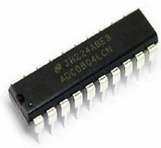
ADC0804 Single Channel 8-bit Analog to Digital Converter
SKU: SKU: DBS153,TMD,Th,KRT
ADC08048-bit A/D Converter [National Semiconductor – Original]
Pin Configuration
| Pin Number | Pin Name | Description |
| 1 | Chip Select (CS) | Chip select is used if more than 1 ADC module is used. By default grounded |
| 2 | Read (RD) | Read pin must be grounded to read the Analog value |
| 3 | Write (WR) | Write pin should be pulsed high to start data conversion |
| 4 | CLK IN | External clock can be connected here, else RC can be used for accessing internal clock |
| 5 | Interrupt (INTR) | Goes high for interrupt request. |
| 6 | Vin (+) | Differential Analog input +. Connect to ADC input |
| 7 | Vin (-) | Differential Analog input -. Connect to ground |
| 8 | Ground | Analog Ground pin connected to ground of circuit |
| 9 | Vref/2 | Reference voltage for ADC conversion. |
| 10 | Ground | Digital Ground pin connected to ground of circuit |
| 11 | Data bit 0 to bit 7 | Seven output Data bit pins from which output is obtained |
| 12 | CLK R | RC timing resistor input pin for internal clock gen |
| 13 | Vcc | Powers the ADC module, use +5V |
Features
- Easy to interface with all Microprocessors or works Stand alone.
- Single channel 8-bit ADC module
- On chip Clock available, no need of external Oscillator (Clock)
- Digital output varies from 0 to 255
- Differential analog voltage inputs
- 0V to 5V analog input voltage range with single 5V supply
- Compatible with 8080 Microprocessors
- When Vref = 5V, for every 19.53mV of analog value there will be rise of one bit on digital side (Step size)
- Available in 20-pin PDIP, SOIC packages
- Logic inputs and outputs meet both MOS and TTL voltage level specifications
- Works with 2.5V (LM336) Voltage Reference
- On-chip clock generator
- No zero adjust required
- Operates ratiometrically or with 5 Vdc, 2.5Vdc, or analog span adjusted voltage reference
Note: Complete Technical Details can be found at the datasheet give elsewhere on this page.
ADC0804 Equivalent ICs
ADC0808, ADC modules
Where to use a ADC0804
The ADC0804 is a commonly used ADC module, for projects were an external ADC is required. It is a 20-pin Single channel 8-bit ADC module. Meaning it can measure one ADC value from 0V to 5V and the precision when voltage reference (Vref –pin 9) is +5V is 19.53mV (Step size). That is for every increase of 19.53mV on input side there will be an increase of 1 bit at the output side.
This IC is very Ideal to use with Microprocessors like Raspberry Pi, Beagle bone etc.. Or even to use as a standalone ADC module. Every ADC module requires a clock to function; this IC comes with its own internal clock so you don’t have to worry about it. Hence, if you are looking for a compact ADC module with a decent resolution of 8-bit then this IC is for you.
How to use ADC0804
Since the IC comes with an internal clock we do not need many components to make it work. However to make the internal clock to work we have to use a RC circuit. The IC should be powered by +5V and the both ground pins should be tied to circuit ground. To design the RC circuit simply use a resistor of value 10k and capacitor of 100pf (approx) and connect them to CLK R and CLK IN pins as shown in the circuit below. The chip select (CS) and Read (R) pin should also be grounded. The Vref pin is left free because by default without any connection it will be connected to +5V.
The digital output will be obtained from the pins DB0 to DB7 and the analog voltage should be connected to V in(+) pin as shown in the circuit. Also note that another end of the voltage source (sensor/module) should also be grounded to the circuit for the ADC conversion to work. Now, for the ADC Conversion to start we have o make the Write(WR) pin to go high momentary this can be done connecting the pin to I/O of MPU and toggling it high before every ADC read. Only if this is done the ADC value on the output side will be update.
In the above circuit I have used a potentiometer to feed in a variable voltage of 0V to 5V to the Vin pin and the present Voltage is read using a voltmeter. As you can see in the image the voltage value is 1.55V and the resulting binary value is 01001111. Let us see how this binary value can be converted to Analog value, since we will need it while programming/designing.
Binary Value = 01001111
Converting to Decimal = (0*128)+(1*64)+(0*32)+(0*16)+(1*8)+(1*4)+(1*2)+(1*1)
= 79
Analog Voltage = Decimal Value * Step size
= 79 * 19.53mV
= 1.54V
The obtained value is 1.54V and the measured voltage is 1.55V which are very much close. So this is how you use an ADC0804 IC.
Applications
- Operates With Any 8-Bit µP Processors or as a Stand-Alone Device
- Widely used with Raspberry Pi, Beagle Bone and other MPU development platforms
- Interface to Temp Sensors, Voltage Sources, and Transducers

